
CCTV Camera Mounting and Positioning
Knowledge Base › CCTV · Last reviewed September 2026 · Connixtech technical team
Camera position decides whether footage is evidence or wallpaper. A 4K camera pointed at the wrong height, into the sun, or covering too wide an area produces images that identify nobody. Resolution does not fix a positioning mistake — pixel density on the target does.
What are the DORI standards for CCTV cameras — and are they still current?
Most CCTV guidance online describes DORI: Detect, Observe, Recognise, Identify, at 25, 62.5, 125 and 250 pixels per metre. That model comes from IEC 62676-4:2014.
IEC published a new edition of 62676-4 on 9 October 2025, replacing the 2014 version. The change is not cosmetic.
The 2014 identification threshold of 250 px/m was set when the reference was a person filling a PAL monitor. In practice it proved insufficient to identify people in low light, with motion blur, or with compression artefacts. The 2025 edition recommends 500 px/m for that task, and renames the level.
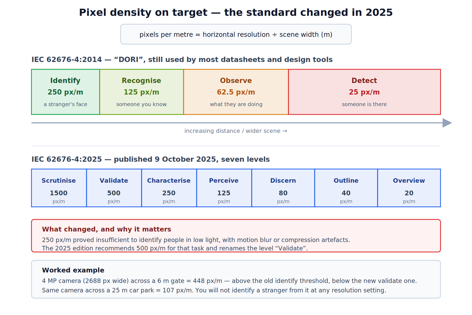
The old ladder (IEC 62676-4:2014) — still in wide use
| Task | Density | What it delivers |
|---|---|---|
| Detect | 25 px/m | Someone is there |
| Observe | 62.5 px/m | What they are doing |
| Recognise | 125 px/m | Someone you have seen before |
| Identify | 250 px/m | Identity beyond reasonable doubt |
The new ladder (IEC 62676-4:2025)
| Level | Density |
|---|---|
| Overview | 20 px/m |
| Outline | 40 px/m |
| Discern | 80 px/m |
| Perceive | 125 px/m |
| Characterise | 250 px/m |
| Validate | 500 px/m |
| Scrutinise | 1500 px/m |
Which should you design to? Both, for now, and know why you chose. Camera datasheets, Axis Site Designer and most lens calculators still use the 2014 DORI values — if a tender or insurer specifies “DORI identification”, they mean 250 px/m. But where identification genuinely matters — a till, a gate, an entry a court might see footage from — treat 250 px/m as the floor and aim for 500. That is the standards body’s own conclusion about what 250 was failing to deliver.
The practical effect is that the identification camera you specified last year is, by the current standard, a “characterise” camera.
How to calculate pixel density
The most valuable camera on most sites is a narrow-field identification camera at a choke point — a doorway, gate or corridor everyone must pass through, at head height. One of those plus a few wide overview cameras beats six mid-height wide-angle cameras every time.
Browse by type: IP Bullet Cameras · IP Dome/Turret Cameras · Fisheye/Panoramic
Mounting height
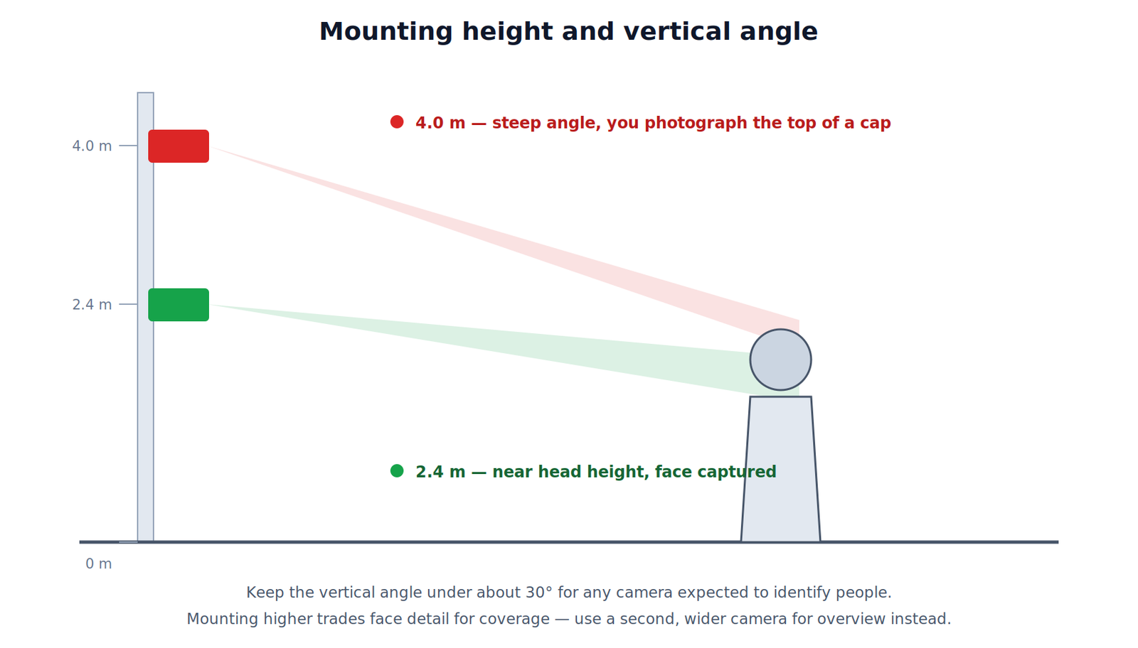
| Purpose | Height | Reasoning |
|---|---|---|
| Facial identification | 2.0–2.5 m | Faces near head-on |
| General overview | 3.0–4.0 m | Out of reach, wide coverage |
| Vandal-prone areas | 3.5 m+, IK-rated | Height plus rated housing |
| Number plate capture | 1.0–1.5 m | Plates are low and near-vertical |
Direction of approach matters as much as height. A face square to the lens yields far more usable pixels than a profile, so mount where people walk towards the camera rather than across it. Where one camera is asked to both identify and give overview, it will do neither well — pair a low camera at the choke point with a higher one for context.
How to read a camera specification: lens and field of view
Narrow lenses see further at higher pixel density; wide lenses cover more with less detail. A varifocal or motorised-zoom camera lets you set the field on site, which is worth the cost wherever the scene is not yet fixed.
| Focal length | Approx FOV | Typical use |
|---|---|---|
| 2.8 mm | ~100–110° | Room overview, entry approach |
| 4 mm | ~80–90° | General purpose |
| 6 mm | ~50–55° | Driveway, corridor |
| 8–12 mm | ~25–35° | Gate identification, car park |
Rule of thumb for a typical 1/2.8″ sensor — check the specific datasheet, since sensor size changes these.
Light: what ruins most installs
- Never point a camera at a window, a west-facing wall at sunset, or an open roller door. The camera exposes for the bright area and everything in front becomes a silhouette. If unavoidable, use true WDR and set it up at the worst hour, not at midday.
- New Zealand winter sun sits low. A camera facing north across a yard will take direct sun in the lens in the middle of a June day. Walk the site with a sun-path app before committing.
- Infrared reflection is the most common night-time failure. Mounted under a soffit, against a wall, or behind glass, the camera’s own IR bounces back and washes the image out. Mount beyond the eave, stand the camera off the wall, or disable built-in IR and use separate illuminators.
- Never mount an IR camera behind glass. It will not work at night.
- Spiders and moths are drawn to IR-lit lenses and will trigger motion recording nightly. Expect to schedule cleaning.
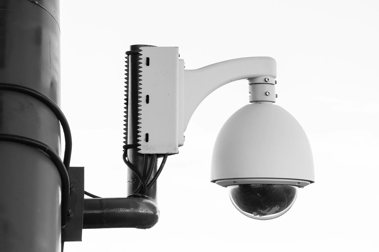
Brackets: Camera Mounting Box/Bracket
Weather and physical install
- IP66 or better externally, with the junction box mounted so cable entry faces downward
- Fit a mounting box on external walls — keeps connectors dry, gives room for spare cable, makes future service possible
- Leave a drip loop before cable enters the camera or box
- Seal the wall penetration properly. Water tracking down a Cat6 into a ceiling space is a common and expensive callback.
- Coastal New Zealand is corrosive. Specify appropriate housing material and stainless fixings within a few kilometres of the coast.
- Fix into structure, not plasterboard alone.
Power and cable
| Standard | PSE output | Device gets | Use |
|---|---|---|---|
| 802.3af (Type 1) | 15.4 W | 12.95 W | Most fixed cameras |
| 802.3at (Type 2) | 30 W | 25.5 W | Heaters, small PTZ |
| 802.3bt (Type 3) | 60 W | 51 W | PTZ with blower |
| 802.3bt (Type 4) | 90 W | 71.3 W | High-power PTZ |
The gap between PSE and device figures is dissipated in the cable over a full-length run.
On “100 W” PoE: the IEEE specification point for Type 4 is 90 W at the port delivering 71.3 W to the device. The 100 W figure in marketing is the SELV per-port ceiling, not the standard’s value.
The Ethernet channel limit is 100 m total, including patch leads at both ends. Plan for 90 m fixed plus 10 m patching. Beyond that use a PoE extender, fibre, or a local switch. Do not use CCA (copper-clad aluminium) — it will not deliver reliable PoE at distance.
See PoE Switches and Network Cables.
New Zealand privacy obligations
CCTV footage of identifiable people is personal information under the Privacy Act 2020. When positioning cameras:
- Cover only what is necessary for the stated purpose. Avoid neighbouring property, public footpaths and residential windows where you can.
- Do not cover areas where people expect privacy — toilets, changing rooms, staff break areas.
- Advise the client that signage is expected practice.
- Advise a documented retention period, applied consistently.
You are the installer, not the client’s privacy officer, but positioning advice is where these problems are cheapest to avoid. Point clients at the Office of the Privacy Commissioner.
Pre-drill checklist
- Purpose written for each camera, and the pixel density target stated
- Pixel density calculated for the actual target distance
- Decision recorded on whether you designed to the 2014 or 2025 thresholds
- Height and vertical angle suit the purpose
- Sun path checked for the worst season, not the install day
- Nothing inside the IR cone within ~1 m
- Cable run under 100 m including patching
- Switch PoE budget covers all cameras plus headroom
- Mounting surface is structural
- No unnecessary coverage of neighbours or public areas
- Client shown the live image and signed off framing before final fix
Always show the client the live view before final fix. Ten minutes on a ladder prevents a return visit.
Specifying cameras for a site? Connixtech’s technical team is available Monday–Friday, 8am–5pm NZT. Email info@connixtech.co.nz or call +64 27 284 7161.
Pixel density figures verified against IEC 62676-4:2025 coverage and Axis white papers, September 2026. PoE figures per IEEE 802.3af/at/bt. Design to the standard your client or insurer specifies.