
Access Control Panel Installation Guide
Knowledge Base › Access Control · Last reviewed September 2026 · Connixtech technical team
An access control panel (also called a door controller) is the device that decides whether a door unlocks. It takes credential data from readers, checks it against a stored user database and time schedule, then switches power to the lock. Everything else on the door — reader, lock, request-to-exit button, door contact — is an input or output wired back to that panel.
This guide covers the physical install and first power-up for standalone and multi-door controllers. Programming credentials is covered separately in Access Control Credentials.
Before you touch a screwdriver: build a door schedule
Most access control call-backs trace to a decision that was never made before install day, not to bad wiring. Write a schedule first — one row per door.
| Door | Lock type | Fail mode | Reader side | REX | Contact | Fire release |
|---|---|---|---|---|---|---|
| Main entry | Electric strike | Fail-secure | Outside | PIR + button | Yes | Via FIP relay |
| Fire stair | Magnetic lock | Fail-safe | Inside | Break-glass | Yes | Direct FIP + break-glass |
| Server room | Electric strike | Fail-secure | Outside | Button | Yes | Not required |
Fail-safe means the lock releases when power is removed. Fail-secure means it stays locked when power is removed. Magnetic locks are always fail-safe. Electric strikes are supplied as one or the other and some are field-convertible.
Safety and compliance. Any door on an escape route must let people out without a key, special knowledge or a working power supply. In New Zealand the requirements for doors and locking devices on escape routes sit in Building Code Clause C (Protection from Fire) and Acceptable Solution C/AS2, which in turn directs escape routes to Clause D1 Access routes. It is often subject to a fire engineer’s specific design. (Clause F6 is Visibility in escape routes — emergency lighting — and is frequently miscited for this.) Confirm the egress strategy with the fire engineer, the building consent authority or the fire alarm contractor before you specify lock type — do not decide it on site. Mains-side work must be done by a registered electrician.
Step 1 — Mount and locate the controller
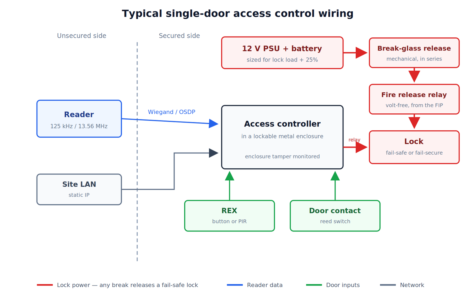
Put the controller inside the secure side of the building, in a lockable metal enclosure, within reach of a permanent power supply and the head-end network.
- Mount at roughly 1.5–1.8 m so the board is serviceable without a ladder.
- Leave 300 mm clear around the enclosure for cable entry and future expansion.
- Never mount the controller on the unsecured side of the door it controls.
- Keep the enclosure away from switchboards, VSDs and fluorescent ballasts — these are the usual source of intermittent reader noise.
- Fit a tamper switch to the enclosure lid and terminate it. On a monitored site this is not optional.
Browse enclosures and controllers under Multi Door Access Control and Stand Alone Access Control.
Step 2 — Size the power supply and battery
Add up the continuous load, then add 25% headroom. A typical 12 V DC door draws:
| Device | Continuous draw |
|---|---|
| Controller board | 100–250 mA |
| Proximity reader | 60–150 mA |
| Magnetic lock (300 kg) | 350–500 mA |
| Electric strike (holding) | 150–300 mA |
| Indoor sounder | 20–40 mA |
Check the actual figures on each datasheet — these are indicative only.
Decide first whether the locks sit on the battery. Fail-safe locks draw continuously through an outage and will dominate the figure; fail-secure locks draw nothing. Size against the load that is actually held up.
Treat that as a floor, not an answer. Sealed lead-acid capacity is quoted at a 20-hour discharge rate; drawing the same battery down over 4 hours returns roughly 75–80% of the rated figure, and a battery at end of service life is down to about 80% again. The 1.25 factor covers the first of those, not both. On monitored or life-safety-adjacent systems, size up and check what the specifying standard requires.
Use a sealed lead-acid battery matched to the charger, and date-label it. See Power supply and Batteries.
Run locks from a separate supply or a separately fused output where the panel allows it. A magnetic lock releasing on a shared rail will brown-out the controller and cause random reboots that look like a firmware fault.
Step 3 — Wire the locks
Cable size matters more than installers expect, because lock current over a long run causes voltage drop and a lock that “sometimes doesn’t hold”.
Figure roughly 0.037 Ω/m for 0.5 mm² (about 20 AWG) and 0.019 Ω/m for 1.0 mm² (18 AWG). Keep total drop under about 10% of nominal, and measure at the lock terminals under load rather than trusting the calculation alone.
Always fit a suppression diode (or the manufacturer’s supplied MOV/varistor) across inductive locks. Without it, the back-EMF spike on release will degrade the relay contacts and can corrupt the controller.
Locks and hardware: Locks.
Step 4 — Wire the readers
Run reader cable back to the controller as a home run. Do not daisy-chain, and do not share a conduit with mains.
- Wiegand readers: 6-core (or more) overall-screened cable. Bond the screen at the controller end only. Keep runs within the manufacturer’s stated limit — commonly around 150 m, less with thinner conductors.
- OSDP / RS-485 readers: twisted-pair screened cable, supports much longer runs (up to around 1200 m on a properly terminated bus) and supports encryption.
Full detail, pinouts and colour codes are in the Access Control Reader Wiring guide. Readers and keypads: Readers, Keypads.
Step 5 — REX, door contact and exit devices
The request-to-exit (REX) device tells the controller a legitimate exit is happening so it releases the lock and suppresses a forced-door alarm. Options are a push button, a PIR exit sensor, or a monitored handle or panic bar.
The door contact (reed switch) tells the controller whether the door is actually closed. Without it you get no door-forced, door-held-open or genuine audit trail — the panel only knows it energised a relay, not that anyone went through. Fit one on every controlled door.
Where the escape route requires it, wire a break-glass emergency release in series with the lock power so it cuts the lock mechanically, independent of the controller. See Exit Devices.
Step 6 — Fire alarm interface
Fail-safe locks on escape routes must release when the fire alarm activates. This is normally a volt-free relay output from the fire indicator panel wired into the lock power circuit so that lock power drops on alarm — not a software input to the access controller.
Interface work on the fire panel is the fire alarm contractor’s scope. Coordinate it, document it, and test it in front of the client at handover.
Step 7 — Power up and commission
- Before applying power, visually check every termination and confirm no shorts between lock supply rails.
- Apply power to the controller only, with lock outputs disconnected. Confirm the board boots and the status LED matches the manual.
- Connect the network, find the controller on the LAN, set a static IP inside the client’s addressing plan, and change the default password immediately.
- Reconnect readers one at a time and confirm each one beeps and reports card reads at the panel.
- Connect lock outputs, then test unlock with a known-good credential.
- Update firmware before you hand over, not after.
Commissioning test checklist
- Valid card unlocks; invalid card denies and logs
- Door contact reports open and closed correctly
- REX releases lock without generating a forced-door event
- Door-held-open alarm fires after the set duration
- Break-glass releases the lock with the controller powered
- Fire alarm activation releases all fail-safe locks
- Mains removed: system runs on battery, locks behave as designed
- Enclosure tamper reports
- Default passwords changed and recorded in the handover pack
- Time and date correct, NTP configured, time zone NZST or NZDT
Common faults and causes
| Symptom | Likely cause |
|---|---|
| Reader beeps, no unlock | Card format mismatch, or user not in an active access group |
| Intermittent reader dropouts | Screen bonded at both ends, or cable run beside mains |
| Controller reboots when lock releases | No suppression diode, or lock sharing the controller supply |
| Maglock will not hold at the end of a run | Voltage drop — conductor too small |
| Door-forced alarms on every exit | REX not wired or not assigned to that door |
| Clock drifts, wrong times in the log | NTP not set |
Frequently asked questions
Can one controller run doors in separate buildings?
Only if the reader and lock cabling stays within spec. Beyond that, use a controller per building on the same network rather than extending a Wiegand run.
Do I need a network connection for a standalone controller?
No. Standalone units store users on the door. The trade-off is no central audit trail and manual re-programming at each door, which stops scaling at around five to ten doors.
Should new installs use Wiegand or OSDP?
Specify OSDP for new work. Wiegand is unencrypted and can be captured and replayed at the reader. OSDP supports Secure Channel encryption and supervises the reader connection.
Need help specifying a system? Connixtech’s technical team is available Monday–Friday, 8am–5pm NZT. Email info@connixtech.co.nz or call +64 27 284 7161. Trade customers can download full manuals from the Downloads page.