
Alarm Zone Configuration and Wiring
Alarm Zone Configuration and Wiring
Knowledge Base › Alarm Systems · Last reviewed September 2026 · Connixtech technical team
A zone is one monitored input on an alarm panel. The panel watches the electrical resistance of the loop and reports a state: sealed, alarm, tamper or fault. How you wire the loop decides how much the panel can tell you.
What do EOL resistors actually do?
Without a resistor, a loop is either made or broken. That is all the panel knows. An intruder who shorts the two conductors together at the detector defeats the zone completely, and the panel reports nothing wrong.
An end-of-line resistor puts a known value in the circuit so the panel measures a specific resistance rather than just continuity. Anything other than that value — higher, lower, open or short — is a fault the panel can report.
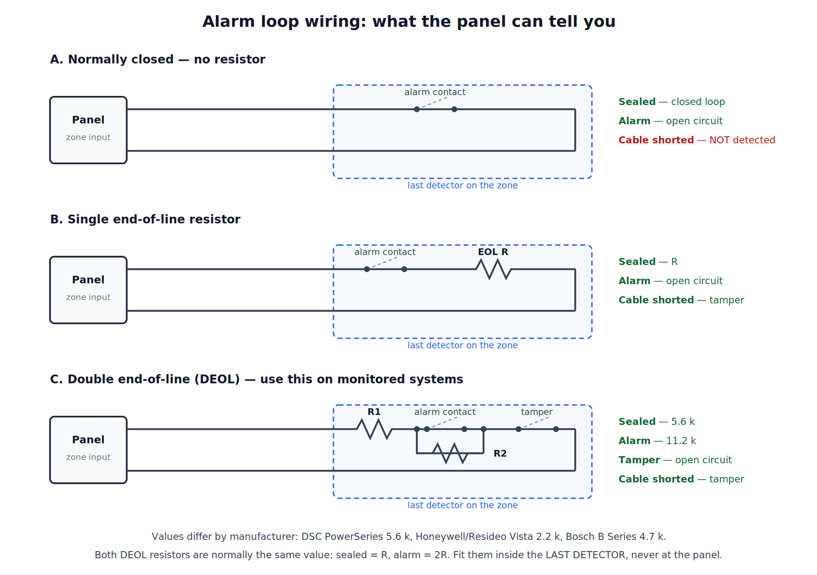
The four wiring methods
| Method | Alarm | Tamper | Short | Cut |
|---|---|---|---|---|
| NC, no resistor | Yes | No | No | Yes |
| Single EOL | Yes | As short | Yes | Yes |
| Double EOL | Yes | Yes | Yes | Yes |
| Triple EOL | Yes | Yes + fault | Yes | Yes |
Use double EOL as the default on any monitored or commercial system. It distinguishes an alarm from a tamper on a single pair of wires, which is what a monitoring station needs to decide on a response.
How does double EOL work?
Two resistors, positioned so the panel sees four distinct states on one pair: one resistor in series with the loop, not shorted by any contact, and one resistor in parallel with the alarm contact, so the closed contact shorts it out.
Using a DSC panel with 5.6 kΩ resistors as the worked example:
| Loop state | Panel measures | What happened |
|---|---|---|
| Sealed | 5.6 kΩ | Alarm contact closed, shorting the parallel resistor |
| Alarm | 11.2 kΩ | Alarm contact open, both resistors in series |
| Tamper | Infinite | Cable cut, or tamper contact opened |
| Fault | 0 Ω | Cable shorted |
That is the whole trick: the closed contact shorts out one resistor, so opening it adds resistance rather than breaking the circuit. Both resistors are normally the same value — sealed is R, alarm is 2R.
What resistor value does my panel need?
This is manufacturer-specific, and getting it wrong means the zone reads permanently faulted or permanently sealed.
Many panels are programmable across roughly 1 kΩ to 22 kΩ, so the value in the box is a default rather than a requirement. Some manufacturers use mismatched pairs — 2.2 kΩ in parallel with 4.7 kΩ, giving a sealed reading near 1.5 kΩ.
Work from that panel’s installation manual. Do not carry a habit from one brand to another.
Does cable resistance matter?
22 AWG copper adds roughly 0.016 Ω per foot, doubled for the return leg. A 150 m loop adds about 16 Ω — negligible against a 5.6 kΩ resistor and irrelevant on a loose-tolerance panel. On a precision or high-security panel with a narrow acceptance window, long runs plus poor joints can push a zone outside tolerance and mimic a tamper.
Where do the resistors go?
At the far end of the loop, inside the last detector. This is the single most common installation error.
A resistor fitted at the panel end provides no protection at all: anyone can cut or short the cable at the detector and the panel still reads the correct value. The resistor has to sit beyond the point an intruder would attack.
- Terminate on the detector’s own terminals, not in a junction box
- Solder or use proper terminal blocks. Twisted-and-taped joints in a ceiling cause the intermittent faults blamed on the panel two years later
- Enable the matching mode in the panel programming as well as wiring it — many panels default to single EOL
Cable: Security Cables
Zone types
| Zone type | Typical devices | Behaviour |
|---|---|---|
| Entry/Exit | Reed on main entry door | Starts the entry timer |
| Access route | Hallway PIR to keypad | Crossable during entry |
| Instant intruder | Internal PIRs | Immediate alarm when armed |
| Perimeter | Window reeds, shock sensors | Active in part-set modes |
| 24-hour | Panic buttons, tampers | Alarms armed or disarmed |
| Key switch | Arming station | Arms and disarms |
Where do false alarms come from?
The zone that generates repeat false alarms is almost always a badly sited detector, not a panel setting.
PIR detectors respond to moving heat. Avoid pointing them at windows in direct sun, heat pumps, heaters, ovens, hot water cylinders, roller doors and skylights that heat rapidly, hanging signage near air movement, and reflective surfaces creating moving light patterns.
Mount at the manufacturer’s specified height — commonly 2.1–2.4 m — and so that intruders cross the detection pattern rather than walking directly at it. PIRs are far less sensitive to movement straight towards them.
- Pet-immune PIRs ignore mass below a threshold at floor level. They fail when the pet climbs furniture into the zone, or when mounted at the wrong height. Discuss the actual animal before specifying.
- Dual-technology detectors require both PIR and microwave to trigger. Worth the cost in warehouses, sheds and areas with heat sources.
- Reed switches must sit within the specified gap. Aluminium joinery and steel doors reduce the effective gap — use a wide-gap reed for steel or roller doors.
- Shock sensors need tuning on site: tap the glass with realistic force, then reduce sensitivity until building movement and passing traffic no longer trigger it.
Devices: Detectors & Devices
Wireless zones
- Signal survey before install. Use the panel’s signal test at each location, doors closed, building in its normal state. Test at the far end of the site, not just near the panel.
- Battery management. Record device locations and battery types in the handover pack.
- Supervision. Enable it, so the panel reports a device that stops checking in. An unsupervised wireless zone that has failed looks exactly like a sealed zone.
Commissioning each zone
- Confirm the loop reads sealed at rest.
- Activate the detector; confirm the correct zone number reports alarm.
- Open the detector cover; confirm tamper reports as tamper, not as alarm. If it reports as alarm, the DEOL wiring or panel setting is wrong.
- Short the loop; confirm tamper or fault.
- Walk test the full pattern and mark the actual coverage.
- Record zone number, location, device type and zone type.
Fault-finding
| Symptom | Likely cause |
|---|---|
| Zone permanently in fault | Wrong value; resistor at the panel end; DEOL not enabled |
| Zone permanently sealed | Resistor across the panel terminals |
| Tamper reported as alarm | Single EOL wiring on a DEOL-programmed panel |
| Intermittent in wind or rain | Poor joint in a cavity; water in a termination |
| Random night activations | Heat source, sun on a roller door, insect in housing |
| Long zone reads marginal | Cumulative cable resistance plus poor joints |
Measurement tip: disconnect the zone at the panel and measure loop resistance at rest, in alarm, and with the cover off. Compare against the manual’s expected values. That isolates a wiring fault from a programming fault in two minutes.
Specifying an alarm system? Connixtech’s technical team is available Monday–Friday, 8am–5pm NZT. Email info@connixtech.co.nz or call +64 27 284 7161. Trade customers can download manuals from the Downloads page.
Resistor values verified September 2026 against published DSC, Honeywell/Resideo and Bosch documentation. Always work to the manual for the panel in front of you.